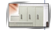
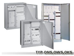
DESCRIPTION OF HOUSING
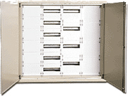
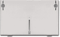
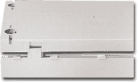
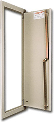
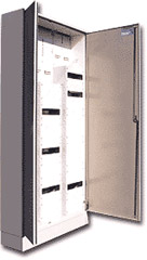
Metal housings in recess-mounted version (OWS - pic.
8), wall-mounted version (ONS - pic. 3) and free-standing version
(OKS - pic. 6, 17) are made of steel sheet, painted with powder
paints (RAL 7035 colour or other, according to customer’s wishes).
Maximal internal width: 4×250 mm
(4 x basic module width) - OWS, ONS, OKS.
Maximal internal height: 8×150 mm
(8 x basic module width) - OWS, ONS.
In case of OKS housing mounted on base, maximal height is
13×height of basic module.
Standard equipment of OWS, ONS and OKS housings includes mounting
channel sections, made of zinc-coated sheet, sheet screws for fixing
of counter boards, mounting sheets and protecting panel brackets.
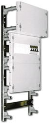
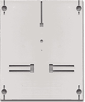
INTERNAL CONSTRUCTION
Arrangement of channel sections in internal
construction allows for mounting of protecting panel brackets for
counter boards as well as mounting of mounting sheets and TS 35
strips (eurorails).
|
The construction of channel
sections allows, due to appropriate arrangement of holes,
for screwing of brackets in any place, depending on
construction and assembly needs.
Internal construction is fixed to the housings with screws,
which facilitates its removal outside and mounting of
modular equipment.
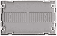
Dimensions of the basic module are: 250 mm width, 150 mm
height. Our offer includes also protecting panels of
dimensions: width 250 mm, height 225 mm, (with “weakened”
places, which facilitate cutting out of a hole, of proper
size, for electrical equipment). |
ASSEMBLY
Brackets (WP) are fixed to internal
construction channel sections (CMY) with sheet screws (BL).
Protecting panels (P1) are mounted with screws (SP), directly on
brackets, with possibility of sealing with lead. In order to
increase the distance from CMY channel section level, extensions of
brackets are applied and they are screwed directly into the brackets,
without using of any tools.
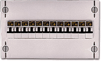
The counter board is mounted directly on CMY channel section, with
sheet screws, which are covered with [ZP] cap, filling the hole.
The offer of H. Sypniewski company includes the counter board
(TL-1F) for monophase counter and the counter board (TL-1F+TLG) for
three-phase counter.
Counter boards are joined without using of tools and additional
fastening elements, because TLG is equipped with special catches,
which join both parts together in a rigid way.
Protecting panel - internal side
Protecting panel with protections
TLG counter board
TL-1F counter board
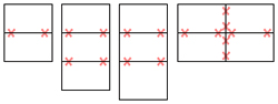
Neighbouring protection panels (P1-1,0 and
P1-1,5), which are mounted at the same depth, can be joined together
with a fastener of protections (so-called "swallow tail "), which
reduces costs of performing of complete housing. Combinations of
joining of individual panels are presented on the figure below:
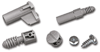
assembly elements
In case of recess-mounted housings, doors are
mounted on screwed collar. In order to install the housing, the
collar should be unscrewed and then the box should be insert into a
recess. Then the gaps between walls of the housing and the recess
should be filled with polyurethane foam. Then fix the collar with
the door, with four screws.
In case when neighbouring protection panels
(P1) are mounted at different depth, then the hole, which is between
the levels, is covered with side covers.
The construction of side covers [PB] allows for direct access to the
parts being under voltage.
CLOSURE OF HOUSING
Doors are closed in two points – in lower and
upper part. A lock of N-1 type is applied. In case of housings of
greater width double doors are mounted.
DESIGNATION OF HOUSING TYPE
Designation of housing type contains three blocks:
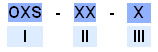
Block I – construction of housing
ONS – housing for wall-mounting
OWS – housing for recess-mounting
OKS – free-standing housing
Block II – designation of manufacturing number
|
Manufacturing
no. |
01 |
02 |
03 |
04 |
05 |
06 |
07 |
08 |
09 |
10 |
11 |
12 |
13 |
14 |
15 |
16 |
17 |
|
Housing width |
300mm |
550mm |
|
Height |
500 |
650 |
800 |
950 |
1100 |
1250 |
500 |
650 |
800 |
950 |
1100 |
1250 |
1400 |
1550 |
1700 |
1850 |
2000 |
|
Number of
modules on the width |
1 |
2 |
|
Number
ofmodules on the height |
3 |
4 |
5 |
6 |
7 |
8 |
3 |
4 |
5 |
6 |
7 |
8 |
9x |
10x |
11xx |
12xx |
13xx |
|
Number of doors |
1 |
|
Manufacturing
no. |
18 |
19 |
20 |
21 |
22 |
23 |
24 |
25 |
26 |
27 |
28 |
|
Housing width |
800mm |
|
Height |
500 |
650 |
800 |
950 |
1100 |
1250 |
1400 |
1550 |
1700 |
1850 |
2000 |
|
Number of
modules on the width |
3 |
|
Number
ofmodules on the height |
3 |
4 |
5 |
6 |
7 |
8 |
9x |
10x |
11xx |
12xx |
13xx |
|
Number of doors |
2 |
|
Manufacturing
no. |
29 |
30 |
31 |
32 |
33 |
34 |
35 |
36 |
37 |
38 |
39 |
|
Housing width |
1050mm |
|
Height |
500 |
650 |
800 |
950 |
1100 |
1250 |
1400 |
1550 |
1700 |
1850 |
2000 |
|
Number of
modules on the width |
4 |
|
Number
ofmodules on the height |
3 |
4 |
5 |
6 |
7 |
8 |
9x |
10x |
11xx |
12xx |
13xx |
|
Number of doors |
2 |
x – regards only OKS housings
xx – regards only OKS housings (in preparation)
NOTICE: OKS housings are performed at the number of
modules at the height >=5
Block III – determination of housing depth
ONS, OWS housings: O – depth 150mm, L – depth 225 mm
OKS housings: L – depth 225mm
|