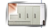
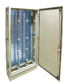
The construction of housings
D-W type housings are metal housings, made of steel sheets 2.0 mm
thick and painted with powder paints using RAL 7035 light-grey
colour or any other RAL colour.
The housings are to be installed on a base, as free-standing,
by-the-wall housings. The construction of the housing is of
prefabricated profiles, with a profiled roof, all elements properly
welded. The profiles have holes perforated and the roof has cuts for
membrane insulation cable penetration, to put out lines or cables.
The height of the base is 100 mm. For higher (200 mm) bases enable
us to install closed holes. The construction of the housing is
enables mounting a rack from profiled and perforated U-irons. The
housing have profiled side-walls screwed from each side. Side-walls
are easy to remove, so the housings could easily be connected. The
back-wall is made of zinc-coated sheet and is supposed to act as the
housing's wall or a mounting board.
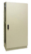
The housing can be made without the back-wall or without the back,
depending on its purpose and function. Its door is deep-profiled,
have a poured seal and hidden hinges. Easily removed hinges enable
the user to dismantle the door easily.
The construction of the hinges let the door be open up to 135
degrees wide. The housings are closed using HS rotating bar
three-point lock. The rack within the housing is prepared for the
module division. The module: width x height (250 x 150 mm).
The insulation material covers constitute of angle profiles from
corners and a board 3 mm thick. By cutting the angle profiles to
proper length, three different covers of different measurements can
be achieved after mounting, Mounted covers have snap screws in the
corners. This solution enables fast mounting (pushing in the screw)
and dismantling, using only a screwdriver. The screws are adapted to
sealing.
The rack is made from vertical perforated profiles; profiles' depth:
roof, side and floor depth (lower).
To connect profiled construction elements, the properly perforated
supports (mounting profiles) are used. They are produced in
different ways depending on the elements to be connected and their
destination. The holes in the rack's profiles are to help properly
aim the supports of the covers. The construction of housing and rack
might seem complicated but its deliberate. It helps mount the system
of cumulative and distributive buses and to prepare a modular
"Promes" system of low-voltage switching station.
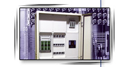
Cumulative buses
The most important part of the high-voltage switching stations,
prepared to switch current are the cumulative buses systems. In the
D-W type housings cumulative buses system is used.
System is easy to use, because is comprises of:
- zinc buses of sections prepared to suit the load
- insulating cantilevers for the cumulative buses of suitable
types
- complete mounting sets.
The cumulative buses sets in the "Promes" system use the following
types of cantilevers:
- ST-3 for the current of 250, 400, 630 A
- UST 4 for the current of 800, 1250, 1500 A
- UST 5 for the current of 1500 do 4000 A
- UST5/4 for the current of 2000A do 4500 A
- special sets for the current up to 6300 A
Bus bridges are mounted in such way that the edges of the zinc buses
are always of the same depth. This allows mounting the cumulative
buses of 2500 A maximum in housing with 600 mm of depth. The
cumulative buses sets for a larger current are mounted in housings
with 800 mm of depth.
Bus bridges are mounted using zinc buses (for the needs of
electro-technique) using original cantilevers and system mounting
sets. Using tested and checked solutions within the construction of
bridge buses and supporting elements allows to produce a switching
station which would suit the EN60439-1 norm.
The tests of cumulative buses have been performed by the KE MA
within the field of the resistance to measured surge current (I pk)
and of the resistance to short-term one-second current (Icu 1 second)
- with good results.
Bridge buses have the obligatory short-circuit strength and ensure
safety of work in low-voltage switching stations.
Neutral protective buses and PEN are mounted on system cantilevers.
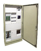
Designation and basic parameters of standard
free-standing housing
|
Standard production |
|
Level of protection |
IP 41 (IP 54 -
special production) |
|
Colour: |
RAL 7035 -
light-gray |
|
Locks: |
Rotating bar
three-point lock |
|
Door: |
Opening angle = 135
Door can be left-sided or right-sided, hidden hinges,
prepared to fast mounting |
|
Construction: |
Construction from
steel sheet - 2 mm thick |
|
Cover |
Powder painted -
approximately 90 μm thick |
|
Inside measurements: |
Measurements of the
module: 250 mm wide/ 150 mm high according to DIN 43 870,
part 2 |
|
Security regulations: |
According to VDE
0100, part 410 Direct touch protection: housing protection
level IP 31 (with he door open) Indirect touch protection: 1
protection class, earthing system
|
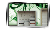
Housing elevation
Housing elevation is mounted from insulation covers. The covers
can be full or have holes to suit the mounted machinery.
D-W housing are prepared to the mounting machinery of different
national i foreign companies:
- switch fuses - NH 00/160 A, NH 1/250 A, NH 2/400 A, NH 3/630
A to be mounted on a mounting plate or a bus
- strip switches VERTIGROUP type mounted on a bus
- fuse base components 24 A i 63 A mounted on a bus
- SILAMAT insulating switch components of 125 to 1600 A with
lever action
- SILAMAT insulating switch components of 80 to 630 A with
rotary action
- TERASAKI compact components Tembreak - 3-field or 4-field
from 63 to 1600 A
- counter boards
- measuring devices components
Designation and measurements of metal housings
D-W type
|
Lp. / Item |
Oznaczenie szafy
/ type housing |
Szerokość / width
[mm] |
Wysokość / height
[mm] |
Głębokość / depth
[mm] |
| 1 |
DW 35-19-4 |
350 |
1900 |
400 |
| 2 |
DW 35-19-6 |
350 |
1900 |
600 |
| 3 |
DW 60-19-4 |
600 |
1900 |
400 |
| 4 |
DW 60-19-6 |
600 |
1900 |
600 |
| 5 |
DW 85-19-4 |
850 |
1900 |
400 |
| 6 |
DW 85-19-6 |
850 |
1900 |
600 |
| 7 |
DW 110-19-4 |
1100 |
1900 |
400 |
| 8 |
DW 110-19-6 |
1100 |
1900 |
600 |
| 9 |
DW 135-19-4 |
1350 |
1900 |
400 |
| 10 |
DW 135-19-6 |
1350 |
1900 |
600 |
Other components of the freestanding housing D-W
type
a) Side walls
|
Lp. / Item |
Szerokość / width
[mm] |
Wysokość / height
[mm] |
| 1 |
Bok szafy
Side of the housing |
400
600 |
1900 |
| 2 |
Ścianki
boczne
Side walls |
302
502 |
1827 |
b) Roof of the housing and bottom of the housing have holes
prepared for "GM" cable penetration
|
Lp. / Item |
Wymiary szafy / housing dimentions |
Ilość przepustów
Number of penetrations |
Szerokość / width
[mm] |
Głębokość / depth
[mm] |
| 1 |
350 |
400
600 |
1900 |
| 2 |
600 |
400
600 |
1900 |
| 3 |
850 |
400
600 |
1900 |
| 4 |
1100 |
400
600 |
1900 |
| 5 |
1350 |
400
600 |
1900 |
c) D-W housing plinth
|
Lp. / Item |
Cokół / Plinth |
Szerokość / width
[mm] |
Wysokość / height
[mm] |
Głębokość / depth
[mm] |
| 1 |
pełny lub otworowany /
standard on with entry hole |
350 |
100 |
400 |
| 600 |
| 200 |
400 |
| 600 |
| 2 |
pełny lub otworowany /
standard on with entry hole |
600 |
100 |
400 |
| 600 |
| 200 |
400 |
| 600 |
| 3 |
pełny lub otworowany /
standard on with entry hole |
850 |
100 |
400 |
| 600 |
| 200 |
400 |
| 600 |
| 4 |
pełny lub otworowany /
standard on with entry hole |
1100 |
100 |
400 |
| 600 |
| 200 |
400 |
| 600 |
| 5 |
pełny lub otworowany /
standard on with entry hole |
1350 |
100 |
400 |
| 600 |
| 200 |
400 |
| 600 |
| On special order we can make entry hole in plinth
with covers. |
d) D-W housing equipment components of the D-W housing
- frame - full supporting structure full supporting structure
for mechanisms distribution and for bus bars (see point 2)
- hollow insulators - full and perforated
GM cable penetration
On the roof and bottom of the housing, on
customer's request, we mount membrane cable penetration, made from
insulating material to
achieve IP 54.
We also provide, free of charge,
computer-designed switching station - according to the schemes given
by the customer
In order to be processed and realized, the Project that should be
provid ed must include:
1. One-line scheme of the switching station, including:
- current propagation in main bus bridges and current
propagation divided into circuits
- type of protection
- type of the mechanisms within the equipment
- circuits main divisions
2. The placement of the switching station must be defined, including
the room placement (freestanding, by-the-wall placement, standing in
line).
- The project prepared by Firma H. Sypniewski, using our
designing tools will include:
- switching station description an d function
- destination and general characteristics
- the scheme, corrected according to our technological
abilities.
- placement of the apparatus defined in the scheme
- switching station's elevation with the door open
- the elevation and choice of cover panels
- basic devices set,
- accordance declarations after the making of a switching
station
- preliminary evaluation and realization time
|